Autopapyrus · Volkswagen Multivan 2.0 TDI CXHA (2017)
https://autopapyrus.com/guides/volkswagen/multivan/complete-engine-overhaul/
https://autopapyrus.com/guides/volkswagen/multivan/complete-engine-overhaul/
Compiled automatically from service literature and owner experience. Specs are for the typical configuration — check them against your exact car before you start.
Volkswagen Multivan 2.0 TDI CXHA (2017): Complete Engine Overhaul
The CXHA is a diesel from the EA288 family (2.0 TDI, 150 hp) with a cast iron cylinder block, 16 valves and a timing belt. The overhaul includes removing the engine, complete disassembly, inspection and measurement of the block, crankshaft and cylinder head, boring and honing of the cylinders, replacement of the pistons and rings, bearing shells and valve stem seals, and then assembly with staged tightening. I do not have verified torque values or dimensions for this model. So below you will find the work sequence and ranges, and you should check the exact figures against the manufacturer's service manual.
Parts
21| № | Part | Genuine part no. |
|---|---|---|
| 01 | Piston set with rings and wrist pins (oversize if boring, standard if honing) | N10133301 |
| 02 | Connecting rod bearing shell setoversize if needed | 04L105701C |
| 04L105701B | ||
| 03 | Main bearing shell setoversize if needed | 04L105561D |
| 04L105561E | ||
| 04L105591D | ||
| 04L105591E | ||
| 04 | Crankshaft thrust washers | 026198421 |
| 05 | Valve stem seals (set for 16 valves) | 04E109675A |
| 06 | Full engine gasket set | |
| 07 | Cylinder head gasketcorrect thickness | 04L103383AM |
| 04L103383AN | ||
| 04L103383AP | ||
| 08 | Cylinder head boltssingle-use, stretch type | WHT007433 |
| 09 | Connecting rod boltssingle-use, stretch type | 045105425 |
| 10 | Crankshaft pulley boltsingle-use, stretch type | WHT005322 |
| 11 | Flywheel boltssingle-use, stretch type | N90665001 |
| 12 | Timing belt kit with rollers | |
| 13 | Water pump | |
| 14 | Crankshaft seals | 04L103151 |
| 04L103171 | ||
| 15 | Oil pumpdepending on condition | 03L115105B |
| 16 | Engine oil | |
| 17 | Oil filter | 03N115389P |
| 03N115562 | ||
| 18 | Coolant | |
| 19 | Oil coolerif lubrication and cooling systems are contaminated | 03N115389P |
| 20 | Heat exchangerif lubrication and cooling systems are contaminated | |
| 21 | Turbochargerdepending on condition | 04L253014C |
Part numbers are from the manufacturer's original catalogue. Check them against your VIN before ordering.
Tools
15- Lift
- shop crane or engine hoist
- engine stand
- torque wrench (5-200 N·m (4-148 lb-ft) range)
- angle gauge for angle-torque tightening
- bore gauge
- micrometers
- feeler gauge
- Plastigage
- EA288 timing locking tools
- seal puller and seal installers
- valve spring compressor and valve keeper tool
- hone and boring machine (machine shop)
- Torx and XZN (multi-spline) socket set
- supplies for cleaning mating surfaces
 There's a full repair manual for this car
Every system, wiring diagrams and torque specs — not just this job. Haynes and 5 more.
See manuals →
Step by step
18 steps- Diagnostics before disassembly. Make sure an overhaul is really needed: measure the compression in each cylinder and the oil pressure, and check how oil consumption is growing and whether there is smoke. Check the turbocharger for shaft play and oil getting into the intake, and rule out worn valves or injectors. If the oil in the system is black with metal particles, be prepared to flush the oil passages, replace the oil cooler and inspect the turbocharger.
- Preparation. Disconnect the negative battery terminal and drain the oil and coolant. Remove the engine undercover and the front bumper with the radiator support frame (on the T6 the engine is usually removed upward rather than downward, but confirm the method as you go). Disconnect the A/C without opening the circuit if you do not have recovery and recharging equipment, and the hydraulics if they are in the way.
- Engine removal. Disconnect all the wiring harness connectors, the fuel lines (carefully, they are under pressure), the intercooler and coolant hoses, and the transmission drive. For a manual transmission, remove the transmission together with the clutch; a DSG requires separate preparation. The engine is removed either with its ancillaries or without them, depending on the shop's procedure. If you are not sure how to safely disassemble the Common Rail fuel system, take the car to a repair shop.
- Disassembly. Mount the engine on the stand. Remove the ancillaries, the timing belt (with the shafts locked), the cylinder head (loosen the bolts in the reverse of the tightening sequence, in several passes), the oil pan, the oil pickup tube and the oil pump. Before removing the pistons, mark the pistons and connecting rods by cylinder. Push the pistons out upward, and remove the crankshaft after marking the main bearing caps.
- Block inspection. Clean the block and flush the oil passages, then check the cylinder head mating surface for warping with a straightedge and feeler gauge. Measure the cylinders with a bore gauge in two planes and at three levels: out-of-round, taper and wear. The nominal cylinder diameter of the EA288 2.0 is about 81 mm (exact value and tolerances: see the manufacturer's service manual). With slight wear and scoring, honing to the standard size is enough; with noticeable wear, bore to an oversize. First check the availability of oversize pistons with the supplier: the pistons of the required size must be in hand before you hand the block over for boring.
- Boring and honing. The block goes to the machine shop together with the new pistons: the cylinders are bored and honed to the actual piston size, allowing for the installation clearance specified by the piston manufacturer. Honing is done with a cross-hatch pattern at an angle, which is critical for ring break-in. After the machine shop, wash the block thoroughly with hot water and detergent, blow out the passages and coat the cylinders with oil.
- Crankshaft. Measure the journals (main and rod) with a micrometer for out-of-round and wear. If wear is within tolerance, grinding is not needed; otherwise grind to an undersize and use the matching bearing shells. Check the axial play and runout. Select the bearing shells based on the measured clearance (Plastigage, or micrometer plus bore gauge), not by the number on the old shells.
- Cylinder head and valve stem seals. Disassemble the cylinder head by compressing the valve springs and replace the valve stem seals with new ones, marked for intake and exhaust (if they differ). Check the valve stems and guides for play, the seats and valve faces for wear, and the head surface for warping. If the guides or seats are noticeably worn, have them repaired at a machine shop. Lap the valves if the seats are in good condition. Measure the springs for length and force. Assemble the head with only a small amount of oil on the stems.
- Bottom end assembly. Install the bearing shells in the bores and caps, lubricate them with engine oil and lay in the crankshaft. Install the main bearing caps by their marks and in the correct direction. The main bearing bolts are single-use, tightened in several stages with angle tightening. As a reference from similar diesels: about 40-50 N·m (30-37 lb-ft), then 70-90 N·m (52-66 lb-ft), then an additional turn of roughly 90-110°, but take the exact values for the CXHA from the service manual. Check that the shaft turns freely after tightening.
- Pistons and connecting rods. Stagger the ring gaps around the circumference at about 120° (diesel rings: the top one is the compression ring, the second is a scraper oil ring, and the third is an oil ring with a spring), lubricate the cylinders and rings with oil, and fit the ring compressor. Orient the piston by the arrow or mark on the crown (toward the timing belt side) and by the combustion chamber. Replace the connecting rod bolts with new ones. The connecting rod caps are tightened in two stages: about 25-35 N·m (18-26 lb-ft) and then an additional turn of about 90° (exact value: see the service manual). Check that the crankshaft turns freely after each connecting rod.
- Piston protrusion above the block surface. Measure the protrusion of each piston at TDC with a dial indicator. Based on the maximum value, select the cylinder head gasket thickness by its marking (notches or holes). This is a critical step: the wrong thickness causes either piston-to-valve contact or a loss of compression.
- Installing the oil pump, oil pickup tube and oil pan. Replace the seals and crankshaft seals (front and rear). Install the oil pan on sealant, applying it according to the procedure, and tighten the fasteners in the range of 8-15 N·m (6-11 lb-ft) in a pattern from the center outward (the exact value depends on the bolt size).
- Cylinder head. Clean the mating surfaces, fit the new gasket of the correct thickness and set the head on the dowels. The cylinder head bolts are single-use, tightened in stages with several angle turns in a pattern from the center outward. A typical sequence for diesels of this family is: 30 N·m (22 lb-ft), then 60 N·m (44 lb-ft), then an additional turn of about 90°, and another turn of 90° (check the service manual for the CXHA, as the figures may differ). Before installing the bolts, make sure the threaded holes in the block contain no fluid.
- Timing. Set the marks using the locking tools, fit the new timing belt, rollers and water pump. Turn the crankshaft two revolutions by hand and check that the marks line up. Belt tension: see the service manual, using the tensioner mark as a guide. Tighten the crankshaft pulley with a new bolt using the angle-tightening procedure.
- Ancillaries. Install new manifold gaskets, the intake and exhaust manifolds, the turbocharger (pour oil into it and turn it by hand before installation, and replace the oil feed line and the screen filter), the injectors with new sealing washers, and the fuel rail. Always check the injector and high-pressure pump torque values against the manufacturer's procedure, as they are very sensitive. A new oil filter and a dry, clean intake are mandatory.
- Engine installation. Install the clutch and flywheel (if removed) with new bolts, set the engine in place and connect the transmission, mounts, wiring harness, and the fuel and coolant lines. Fill with oil meeting the VW specification for diesels with a particulate filter (low SAPS, 5W-30 VW 507.00 or an equivalent per the manufacturer's specification, capacity about 5-7 L (5.3-7.4 qt), confirm with the dipstick) and fill with coolant, bleeding the air.
- First start. Before starting, crank the engine with the starter without fuel delivery (disable the fuel supply or unplug the pump connector) until oil pressure appears. Start the engine and monitor the oil pressure, leaks and temperature. Warm it up to operating temperature and check the levels. Read the fault codes with diagnostics and, if necessary, adapt the injectors and reset the adaptations with a diagnostic scan tool.
- Break-in. For the first 1000-1500 km, avoid full loads and prolonged driving at a constant speed, keep the engine below 3000 rpm, and avoid full throttle and cold starts at high revs. Change the oil and oil filter after 1000-2000 km, and after that follow the service schedule. Re-tightening or an additional angle turn of the cylinder head bolts is not required for this procedure if new bolts were used.
Common mistakes and warnings
- This job requires precise measurements, boring and honing equipment, and Common Rail diesel fuel system equipment
- If you have no experience assembling engines, leave the disassembly, measurements and assembly to a repair shop
- Do not reuse the cylinder head, connecting rod, main bearing, crankshaft pulley and flywheel bolts, as they are single-use
- The high-pressure fuel system is dangerous: do not disconnect the lines while the engine is running or right after it stops
- Be sure to check the exact torque values and tightening sequence for the CXHA against the manufacturer's service manual
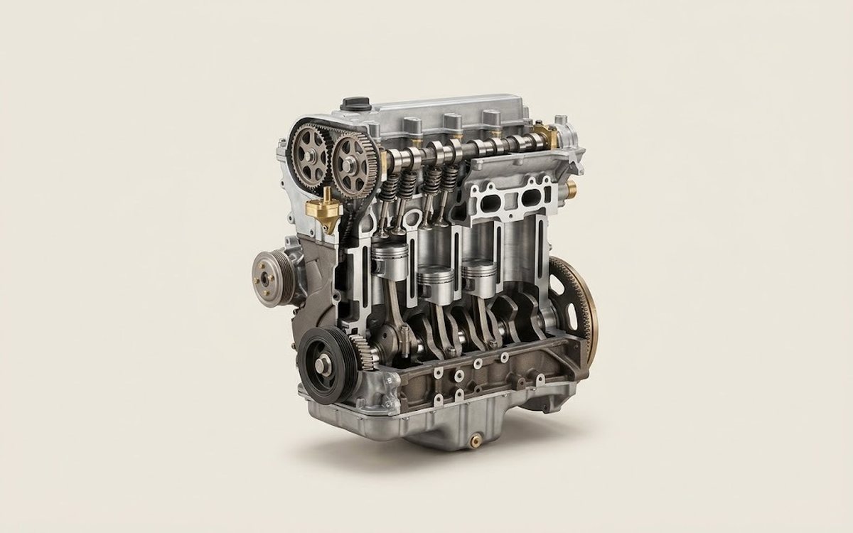 How it works · 3D
How a Car Engine Works
How the part you're working on actually works — in plain English, on a 3D model.
Open in 3D →